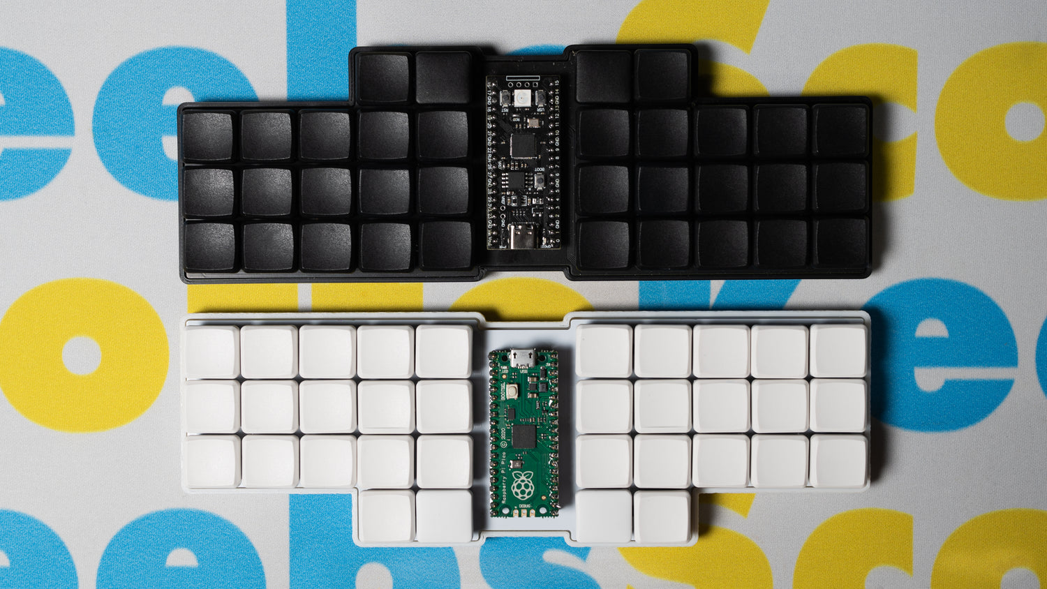
The ScottoKatana is a 33-key katana staggered keyboard with a 6.25u spacebar and two 1.5u function keys. The board uses Gateron Milky Yellows lubed with Krytox 205G0 and is likely my best sounding board yet. The keycaps are fully 3D printed and feel really nice to type on, you can find them here. It comes in two different variant, the integrated plate version and a gasket mount version. Everything is powered off an RP2040 Pro Micro but the board is also compatible with a standard USB-C Pro Micro.
Getting One
If you’re interested in getting one assembled, contact me and we can discuss the components and other details for a commissioned build. However, the files are available for free here if you want to build one yourself.
In addition to the 3D printed case, heat shink tubing, wire, and copper, you'll also need tools along with the following components:
- 1 RP2040 or ATmega32U4 Pro Micro
- 33 1N4148 diodes
- 10 M2x5mm screws
- 10 M2 heat set inserts
- 1 6.25u plate mount stabilizer
- 33 MX switches
- 30 1u keycaps
- 2 1.5u keycaps
- 1 6.25u keycap
Wiring

When looking at the back of the board, the columns (blue) go to the following pins on the controller from right to left: GP3, GP4, GP5, GP6, GP7, GP29, GP28, GP27, GP26, GP22
Then the rows (red) go from top to bottom: GP10, GP0, GP1, GP2
Keep in mind, you can connect anywhere on the column or row to the controller, it doesn't need to just be at the end.
Firmware
You can find the firmware files on the qmk_firmware repository or you can compile them online using the QMK Configurator. However, QMK is often slow at getting changes merged and because of that you can find the most up-to-date firmware on the ScottoKeebs Github repository. Also available are the pre-compiled firmware files that are ready to flash:
default.uf2 - Default QMK keymap in QWERTY.
vial.uf2 - Default QMK keymap in QWERTY with Vial configurator support.
scotto.uf2 - My personal QMK keymap in Colemak.
After flashing vial.uf2, you should load the vial.vil configuration file within the Vial application to ensure everything functions as expected.
Video
Photos


2 comments
The yellow wires connect the left and right rows.
In the final picture, where did the yellow wires come from? The picture above that seems to be all wired up, I’m just confused about the extra yellow (Attempting this as my first handwired board)