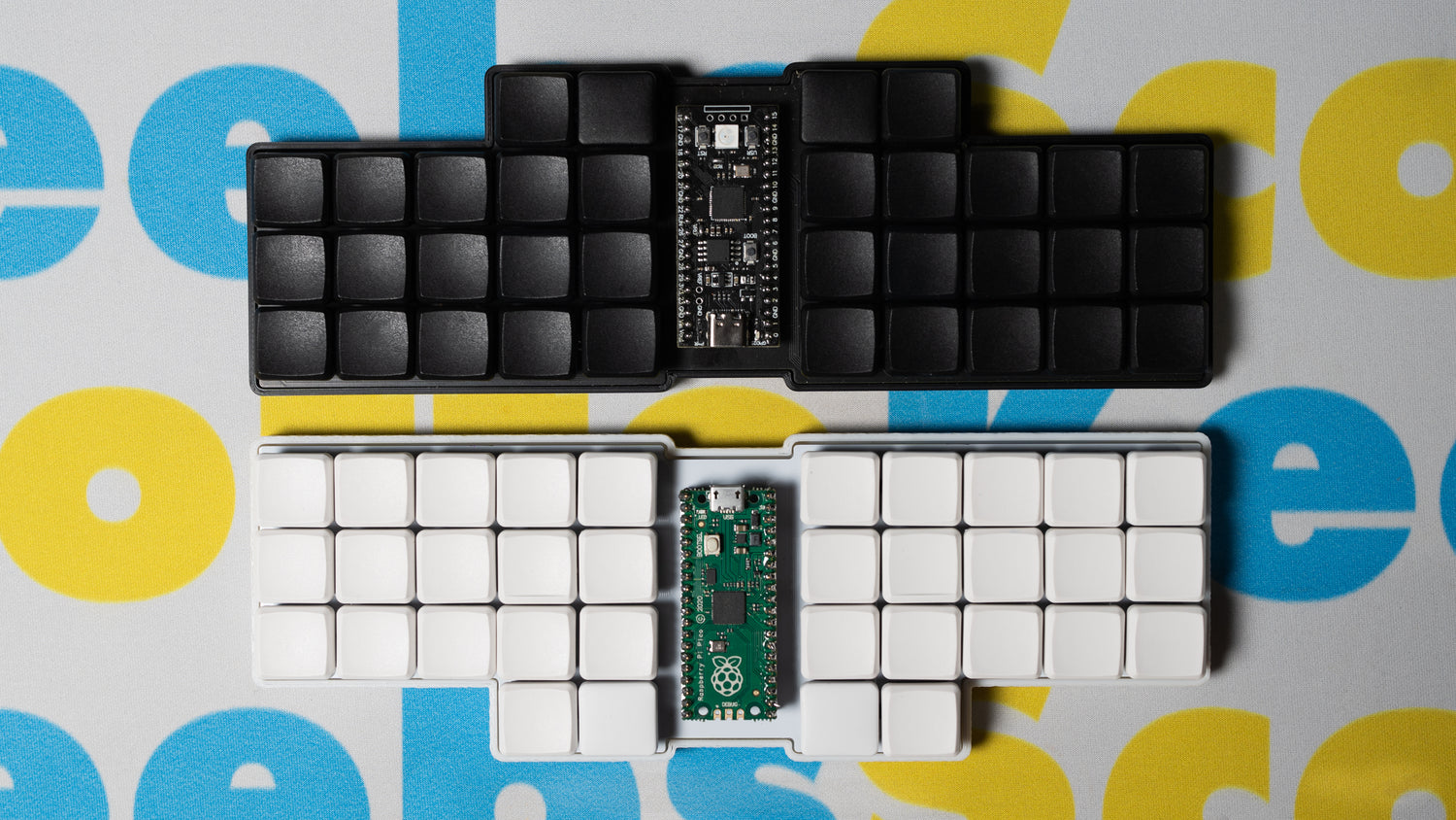
Getting One
If you’re interested in getting one assembled, contact me and we can discuss the components and other details for a commissioned build. However, the files are available here if you want to build one yourself.
In addition to the 3D printed case, heat shink tubing, wire, and copper, you'll also need tools along with the following components:
- 2 RP2040 Pro Micro
- 2 TRRS connectors
- 1 TRRS cable
- 48 1N4148 diodes
- 10 M2x5mm screws
- 10 M2x8mm standoffs
- 48 MX switches
- 48 1u keycaps
Wiring

When looking at the back of the board, the columns (blue) go to the following pins on the controller from right to left for each half: GP4, GP5, GP6, GP7, GP8, GP9
Then the rows (red) go from top to bottom: GP22, GP20, GP23, GP21
The TRRS connector should connect to: VCC, GND, and GP1
Keep in mind, you can connect anywhere on the column or row to the controller, it doesn't need to just be at the end.
Firmware
You can find the firmware files on the qmk_firmware repository or you can compile them online using the QMK Configurator. However, QMK is often slow at getting changes merged and because of that you can find the most up-to-date firmware on the ScottoKeebs Github repository. Also available are the pre-compiled firmware files that are ready to flash:
- default.uf2 - Default QMK keymap in QWERTY.
- scotto.uf2 - My personal QMK keymap in Colemak.
- vial.uf2 - Default QMK keymap in QWERTY with Vial configurator support.
Since this board is split, you should flash each left and right file to the respective side first. Afterwards you can use any non left or right file to flash a new keymap. This is because the board needs to know which half is which and flashing the respective keymap to each side stores it in memory on the controller.
After flashing vial.uf2, you should load the vial.vil configuration file within the Vial application to ensure everything functions as expected.
Video
Photos


1 comment
This is awesome, thanks for sharing!